As the world ramps up its battery deployments, the importance of Industrial Energy Storage Connectors has never been more obvious. These little guys are vital for safety and performance. According to the International Energy Agency’s report in Batteries and Secure Energy Transitions (2024), the added battery storage capacity hit around 42 GW in 2023. That kind of growth really puts pressure on every connection point inside these container systems. Imagine carrying hundreds of amps in a connector, all while battling heat, vibrations, moisture, and sometimes even being handled by crew members. A small mistake in design can lead to costly downtime — it’s that serious.
Getting the right Energy Storage Connector isn’t just about matching voltage or current. You’ve gotta think about cable sizes, how hot things might get, and the enclosure details too. Plus, things like touch protection, lock mechanisms, creepage distances, contact resistance, and how many times the connector can be plugged in without fail — those matter just as much. Standards like IEC 61984 and IEC 60529 give some good frameworks to follow for safety and ingress protection. UL 4128 might also come into play, but don’t just trust a datasheet — you need to verify certifications carefully.
We’ve also got to keep in mind that the costs are still under pressure, according to reports from BloombergNEF, like their Energy Storage System Cost Survey 2024. Cheap parts might seem great on paper, but they could hide weaker plating, poor thermal performance, or tough field replacements down the line. Sometimes, what looks like a simple “plug-and-play” solution isn’t so simple in reality. A connector might snap in nicely physically, but that doesn’t guarantee it’ll work reliably under real-world conditions. This upcoming 2026 guide digs into things like contact materials, high-voltage interlock options, IP ratings, installation methods, and long-term performance. It’s all about practical buying decisions, not just marketing hype. Because let’s face it — field conditions are unpredictable, and many specs don’t really account for that lifecycle chaos.

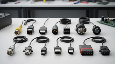
Industrial energy storage Connectors are the physical interfaces between battery modules, busbars, power conversion systems, and monitoring equipment. They carry substantial current while maintaining a secure electrical and mechanical connection. AnEnergy Storage Cable is only as dependable as the connector attached to it.
These connectors help control heat, vibration, moisture, and accidental contact. A loose contact can increase resistance, create hot spots, and damage nearby insulation. That risk grows inside a cabinet where several hundred volts may be present. For this reason, engineers check rated voltage, current capacity, temperature range, ingress protection, and touch safety. They also verify creepage distance and locking performance.
Small details matter. During installation, the terminal should seat fully, the locking mechanism should click, and the specified tightening torque should be followed. Field inspections often reveal discoloration around poorly tightened connections. It is not always obvious at first. A connector may look clean while its internal contact pressure has weakened. Vibration, repeated maintenance, and thermal cycling can expose that weakness later. Good selection therefore considers service access, cable size, polarity protection, and compatibility with applicable electrical standards. A perfect datasheet does not replace careful installation. It is easy to underestimate this component.
Industrial energy storage connectors are defined by operating conditions, not catalog appearance.
Start with maximum DC voltage, continuous current, and short-circuit withstand requirements. Include charging peaks, inverter transients, and allowable temperature rise. A 1,500-volt system needs insulation coordination beyond a 1,000-volt design. The IEA’s 2024 Batteries and Secure Energy Transitions report projects 1,200 GW of battery storage by 2030 in its net-zero pathway. That scale increases the cost of small specification errors. Do not size from nominal current alone.
Measure cabinet heat, humidity, dust, salt exposure, and vibration. For outdoor enclosures, check IP protection, UV resistance, corrosion control, and mating-cycle durability. Cold climates can stiffen seals. Hot cabinets accelerate contact resistance and aging. Use derating curves from verified test data, not optimistic room-temperature values. The U.S. Department of Energy’s 2023 Energy Storage Grand Challenge Roadmap identifies safety, reliability, and materials resilience as core deployment priorities. A useful admission: early specifications are often incomplete.
Tips: Record the highest measured current, not the average. Separate continuous and peak loads. Request test evidence for temperature rise, insulation, and mechanical endurance. Recheck clearance distances after installation. A connector may meet its rating in a laboratory, yet fail after dust, vibration, and repeated maintenance. This is where engineering judgment still matters.
Industrial energy storage systems need connectors matched to current, voltage, enclosure, and maintenance routines. Connector selection changes with each Energy Storage Application. The IEA’s 2024 Batteries and Secure Energy Transitions report estimates that global battery storage capacity must expand to about 1,200 GW by 2030. Reliable connections will become more important.
Containerized lithium-ion systems commonly use high-voltage DC connectors, busbar links, and auxiliary signal connectors. Bolt-on busbar connections suit fixed battery racks with limited servicing. Touch-safe quick-disconnect connectors fit modular cabinets and frequent replacement work. Flow battery systems often need corrosion-resistant power terminals and fluid-compatible sensing connections. UPS systems may favor compact, keyed connectors for controlled installation. Microgrid projects need communication and interlock connectors alongside power contacts. One connector type rarely fits every cabinet.
Tips: Check continuous current, short-circuit withstand, mating cycles, and temperature rise. Leave clearance around locking mechanisms. A connector rated for peak current may still fail under constant heat. Review IEC 61984 and IEC 62933 guidance, then confirm the supplier’s test evidence. Field experience shows that cable bending is often underestimated. It stresses terminals inside crowded racks. NREL’s cost and performance studies also show that storage economics depend heavily on system integration, not cells alone. A perfect connector choice is difficult. Installation drawings may need revision after the first service inspection.
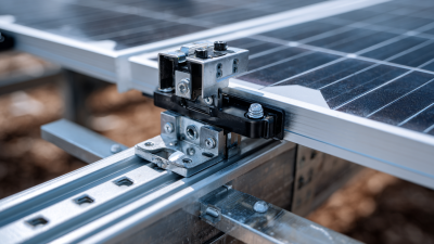
Choosing industrial energy storage connectors starts with material selection, not catalog appearance. Copper provides strong conductivity and stable performance under high current. Tinned copper adds protection in humid battery rooms and outdoor cabinets. Aluminum reduces weight and cost, but requires careful surface preparation. Its oxide layer can increase contact resistance. Select insulation that tolerates heat, vibration, and expected chemical exposure. Solar Energy Cables also need compatible terminals and sealing methods. A connector is only as reliable as its weakest interface.
Contact design affects both heat and maintenance. Flat contacts distribute pressure across a broad area. Spring contacts can maintain force during vibration and thermal cycling. However, spring systems may need stricter cleanliness controls. Crimped connections usually provide consistent electrical performance when tooling is calibrated. Bolted connections support field replacement, but incorrect torque can loosen joints or damage threads. Quick-lock designs save installation time. They still require clear locking feedback.
Tips: Compare temperature rise, current capacity, salt-spray resistance, and service life under realistic loads. Check whether the connection method suits your technicians’ tools. Mark torque values near each bolted joint. Measure resistance after assembly, then repeat testing after thermal cycling. Do not trust appearance alone. I once considered a clean-looking connection acceptable, but a slight crimp deformation later revealed uneven pressure. That mistake changed our inspection routine.
How to Compare Materials, Contact Designs, and Connection Methods
Electrical conductivity is shown as a percentage of the International Annealed Copper Standard (IACS) at approximately 20°C. Higher conductivity generally helps reduce resistive heating and power loss, but industrial connector selection must also consider contact force, corrosion protection, mechanical strength, temperature rating, and installation quality.
Reference values are typical engineering values: copper 100% IACS, aluminum approximately 61% IACS, brass approximately 28% IACS, and stainless steel approximately 2.4% IACS. Actual performance varies by alloy, temper, plating, temperature, joint geometry, and surface condition.
2026 How to Choose Industrial Energy Storage Connectors
In industrial energy storage systems, connector safety starts with controlled contact. Look for touch-safe designs, clear polarity, and secure locking mechanisms. A visible lock indicator helps technicians confirm engagement without pulling the cable. Seals should resist dust, moisture, and cleaning chemicals used around battery rooms. Verify the connector’s voltage and current ratings under real temperatures, not just laboratory conditions. Thermal derating matters during long discharge cycles.
Reliability depends on more than a strong housing. Check contact resistance, vibration performance, insulation quality, and resistance to repeated mating. Connectors should withstand thermal cycling without loosening or cracking. Test reports should match relevant IEC or UL requirements and identify the exact connector configuration. Do not accept a generic certificate. It may not cover your installation.
Maintenance features can reduce downtime significantly. Choose connectors with accessible inspection points, replaceable seals, and clear service markings. A technician should identify damage quickly, even under poor lighting. Keep spare parts protected from dust and humidity. Small details matter. I have seen clean-looking connectors hide heat discoloration near the contacts. That is why infrared checks and torque verification deserve a place in routine maintenance. No checklist is perfect. Operators should record recurring faults and revise inspection intervals when field conditions change. A connector that performs well in a factory test may behave differently near salt air, vibration, or frequent load changes.
| Evaluation Dimension | What to Evaluate | Recommended Evaluation Benchmark | Verification Method | Importance for Energy Storage Systems |
|---|---|---|---|---|
| Voltage Rating | Rated direct-current voltage of the connector and insulation system. | The connector voltage rating should be equal to or higher than the maximum battery-string voltage, including the highest charging voltage and applicable transient margin. Industrial battery systems commonly use 400–1,500 V DC architectures. | Review the datasheet, dielectric-withstand test report, creepage and clearance dimensions, and system-level insulation-coordination calculation. | Insufficient voltage capability can cause insulation breakdown, arcing, equipment damage, or electric shock. |
| Continuous Current Capacity | Current-carrying capability under the actual cable size, ambient temperature, enclosure conditions, and duty cycle. | Select a connector with a continuous-current rating above the maximum operating current after applying temperature, altitude, bundling, and duty-cycle derating. Typical industrial storage power paths may range from tens of amperes to several hundred amperes. | Check current-derating curves and perform temperature-rise testing at the actual cable cross-section and installation arrangement. | Overheating at the contact interface accelerates aging and can create a thermal runaway or fire risk. |
| Touch Protection | Protection against accidental contact with energized contacts during installation, operation, and disconnection. | Use finger-safe construction with no accessible energized parts when the connector is properly mated. Verify the required protection level for both mated and unmated conditions. | Use the applicable finger-probe test and review compliance evidence against the project’s electrical-safety requirements. | Battery strings can remain energized even after part of the system is shut down, making touch protection essential. |
| Ingress Protection | Resistance to dust, water, condensation, and cleaning fluids in the installed configuration. | For outdoor or washdown-prone installations, evaluate an enclosure system capable of at least IP65 when mated; IP67 may be appropriate where temporary immersion is possible. Confirm whether the rating applies only when mated. | Review testing to IEC 60529 or the project’s equivalent requirements, including cable seals, backshells, unused ports, and panel interfaces. | Moisture and contamination can reduce insulation resistance and increase contact corrosion. |
| HVIL and Interlock Capability | High-voltage interlock loop capability that detects an open, improperly seated, or removed connector. | The interlock should open before power contacts separate and close only after the connector is fully seated and mechanically secured. | Inspect the sequencing design, contact timing, retention mechanism, and control-system response during insertion and removal tests. | A correctly designed interlock helps prevent load-break arcing and unintended exposure to high voltage. |
| Locking and Retention | Resistance to vibration, shock, cable pull, and accidental release. | Use positive locking with clear visual or tactile confirmation. The retention system should withstand the specified mechanical loads without partial disengagement or contact interruption. | Review vibration, shock, cable-retention, and unintended-release test results under the installation’s actual orientation. | Partial disengagement can increase contact resistance and generate localized heat. |
| Contact Resistance | Electrical resistance at the mated contact interface and its change after aging. | Require a low initial millivolt-drop or resistance value stated by the manufacturer, with stable results after thermal cycling, vibration, humidity, and mating-cycle tests. | Measure four-wire contact resistance before and after environmental and mechanical durability testing. | A small resistance increase can produce significant heat at high current. |
| Material and Corrosion Resistance | Plating system, base materials, galvanic compatibility, and resistance to salt, humidity, and chemical exposure. | Use contact materials and plating suitable for the environment. Avoid incompatible dissimilar metals and verify resistance to the expected humidity, salt mist, electrolyte vapor, and cleaning agents. | Review material declarations and corrosion-test results; inspect contact surfaces after environmental exposure. | Corrosion raises contact resistance and can compromise both electrical and mechanical performance. |
| Thermal and Fire Performance | Insulating-material flammability, temperature rating, thermal cycling capability, and resistance to abnormal heating. | Select insulation and seals with a temperature rating exceeding the calculated maximum connector temperature. A flame-retardant housing, such as a material meeting a suitable UL 94 classification, should be evaluated for the enclosure design. | Review material certificates, temperature-rise data, thermal-cycle results, and fire-performance documentation. | Thermal margin reduces the likelihood of insulation deformation, seal failure, and ignition. |
| Mating Durability | Number of permitted mating and unmating operations while maintaining electrical and mechanical performance. | The specified mating-cycle life should exceed the expected service activity. Frequently serviced interfaces should use a connector designed for repeated operation rather than a one-time installation connector. | Compare manufacturer cycle-test data with the maintenance schedule and measure contact resistance after cycling. | Wear of contacts, seals, and locks can reduce reliability during routine maintenance. |
| Cable Termination Quality | Crimp, compression, or bolted termination design; conductor compatibility; and strain relief. | The termination method should match the conductor material and cross-section. It should provide controlled compression, clear tooling instructions, and protection against cable bending at the contact. | Use calibrated tooling, pull-force testing, cross-section inspection, and installation records for torque or crimp parameters. | Poor terminations are a common source of high resistance, hot spots, and intermittent faults. |
| Insulation Monitoring Compatibility | Compatibility with insulation-monitoring devices, grounding arrangements, shielding, and leakage-current limits. | Confirm that connector materials, shields, screens, and creepage paths do not create unacceptable leakage or interfere with the system’s insulation-monitoring function. | Perform insulation-resistance and leakage-current checks in the complete battery-rack or power-conversion assembly. | Reliable insulation monitoring helps detect degradation before it becomes a hazardous fault. |
| Maintenance Accessibility | Ease of inspection, access, disconnection, replacement, and correct reinstallation. | Prefer clear locking indicators, service loops, accessible test points, replaceable seals, keyed or polarized interfaces, and sufficient clearance for approved tools and personal protective equipment. | Conduct a maintenance mock-up using the intended enclosure, cable routing, gloves, tools, and work instructions. | Good accessibility reduces service time and lowers the risk of incorrect reconnection. |
| Condition Monitoring | Ability to detect connector temperature, voltage drop, loosening, or insulation degradation. | For high-current or safety-critical circuits, provide a practical method for infrared inspection, temperature sensing, voltage-drop measurement, or connection-status monitoring. | Define inspection intervals and alarm thresholds based on baseline measurements and thermal-design calculations. | Early detection can prevent a developing high-resistance connection from becoming a failure. |
| Standards and Documentation | Applicable connector, enclosure, environmental, battery, and energy-storage safety requirements. | Request traceable test reports and installation instructions covering electrical ratings, mechanical retention, environmental performance, materials, crimping, torque, and inspection requirements. Relevant references may include IEC 61984, IEC 60529, IEC 60068, and applicable energy-storage safety standards. | Check that certificates and test reports apply to the exact connector configuration, contact size, cable range, and mated condition. | Complete documentation supports design approval, audits, installation quality, and long-term maintenance. |
Note: The benchmarks above are practical selection guidelines rather than universal requirements. Final connector ratings and test conditions should be determined from the battery voltage, maximum fault current, cable size, enclosure design, ambient conditions, installation method, applicable regulations, and the complete energy-storage system safety assessment.
Selecting industrial energy storage connectors requires more than matching voltage and current ratings. Verify the applicable IEC, UL, or regional requirements for the complete assembly, not only the connector body. Ask for current test reports, material specifications, and traceable production records. A certificate without a clear scope can create false confidence.
Compatibility should be checked against cable size, insulation diameter, polarity, mating cycles, and thermal rise. Compare the connector with the battery cabinet, busbar, fuse, and inverter terminals. Solar Connectors Photovoltaic Connectors may look familiar, but they are not automatically suitable for high-current storage systems. Check creepage, clearance, touch protection, and the stated DC interruption capability. Small differences matter.
Installation performance depends on disciplined workmanship. Confirm crimp height with a gauge, then perform a pull test on sample terminations. Inspect for exposed strands, damaged seals, and incomplete locking. Torque terminals with a calibrated tool and record the value. Use thermal imaging after commissioning and under realistic load; a warm contact often reveals a weak crimp. No checklist is perfect. Field conditions can still expose gaps. Dust, vibration, and repeated maintenance may change results over time. I would review the installation records after the first operating month, because early assumptions are sometimes wrong. A connector should remain mechanically secure, electrically stable, and cool enough under its actual duty cycle.
Start with maximum DC voltage, continuous current, and short-circuit withstand capability. Separate continuous loads from charging peaks and inverter transients. Do not size from nominal current alone. Record the highest measured current.
Heat increases contact resistance and accelerates material aging. Check allowable temperature rise under realistic loads. Use verified derating curves, not room-temperature assumptions. A peak-rated connector may still overheat continuously.
Measure humidity, dust, salt exposure, vibration, and cabinet temperature. Outdoor systems also need suitable ingress protection and ultraviolet resistance. Cold conditions can stiffen seals. Hot cabinets are less forgiving.
Modular cabinets often suit touch-safe quick-disconnect connectors. Fixed battery racks may use bolted busbar connections. Flow systems need corrosion-resistant terminals and compatible sensing connections. Communication and interlock connectors support microgrid control. One type rarely fits every cabinet.
Verify cable size, insulation diameter, polarity, mating cycles, and thermal rise. Compare the connector with fuses, busbars, batteries, and inverter terminals. Check creepage, clearance, touch protection, and DC interruption capability. Small differences matter.
Confirm crimp height with a suitable gauge. Perform pull tests on sample terminations. Inspect seals, exposed strands, and locking positions. Apply terminal torque with a calibrated tool. Record the value.
Use thermal imaging under realistic operating loads. A warm contact may indicate a weak crimp or loose terminal. Review measurements during the first operating month. Field conditions can still expose gaps.
Early specifications may omit peak currents, vibration, or maintenance conditions. Installation drawings often change after the first service inspection. A laboratory result does not guarantee field performance. My first assumption may be wrong.
Choosing the right Industrial Energy Storage Connectors is essential for building a safe, efficient, and durable energy storage system. This guide explains their role in transferring power and signals between batteries, modules, inverters, and control equipment. It outlines how to determine voltage, current, temperature, moisture, vibration, and installation requirements before selecting a connector. Different connector types are compared according to system structure, power level, space limitations, and service needs.
The article also examines material selection, contact design, locking mechanisms, and connection methods that affect electrical performance and long-term reliability. Key evaluation factors include insulation, resistance to overheating, protection against accidental contact, mechanical strength, ease of maintenance, and suitability for repeated installation. Finally, it explains how to verify applicable standards, system compatibility, cable requirements, and installation performance through inspection and testing. A systematic selection process helps reduce connection failures, simplify maintenance, and support dependable energy storage operation.